Networking and Communication
Individual Assignment
design, build, and connect wired or wireless node(s) with network or bus addresses
Group Assignment
Send a message between two projects
Individual Assignment
This weeks assignment is to create a network using our custom PCB boards and using a wired or wireless
connection. I decided to do led off and on using nodemcu esp 8266 the sending instruction
off and on is sending through mobile. Due lock-down limited access the pcb has not been
prepared however shortly i am caring about this own pcb for the above work.
NodeMCU
The NodeMCU
(Node MicroController Unit) is an open source software and hardware development environment that is built around a very inexpensive System-on-a-Chip (SoC) called the ESP8266.
ESP8266 NodeMCU
The ESP8266 is a low-cost Wi-Fi microchip, with a full TCP/IP stack and microcontroller capability, produced by Espressif Systems in Shanghai, China. The chip first came to the attention of Western makers in August 2014 with the ESP-01 module, made by a third-party manufacturer Ai-Thinker. Wikipedia
The technical highlights and noticeable points of the ESP8266 NodeMCU are:
Easy to use for I0T projects with micro-USB connection and build in WiFi (IEEE 802.11 b/g/n)
Fast processing power with up to 160 MHz compared to 16 MHz for the ATmega328p (Arduino)
The version 2 fits on a standard breadboard so that you can access any pin but because version 3 is wider, it also fits on a breadboard, but you cannot access the pins.
NodeMCU ESP8266 Specifications & Features
- Microcontroller: Tensilica 32-bit RISC CPU Xtensa LX106
- Operating Voltage: 3.3V
- Input Voltage: 7-12V
- Digital I/O Pins (DIO): 16
- Analog Input Pins (ADC): 1
- UARTs: 1
- SPIs: 1
- I2Cs: 1
- Flash Memory: 4 MB
- SRAM: 64 KB
- Clock Speed: 80 MHz
- USB-TTL based on CP2102 is included onboard, Enabling Plug n Play
- PCB Antenna
- Small Sized module to fit smartly inside your IoT projects
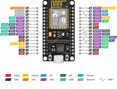
Power Pins There are four power pins viz. one VIN pin & three 3.3V pins. The VIN pin can be used to directly supply the ESP8266 and its peripherals, if you have a regulated 5V voltage source. The 3.3V pins are the output of an on-board voltage regulator. These pins can be used to supply power to external components.
GND is a ground pin of ESP8266 NodeMCU development board.
I2C Pins are used to hook up all sorts of I2C sensors and peripherals in your project. Both I2C Master and I2C Slave are supported. I2C interface functionality can be realized programmatically, and the clock frequency is 100 kHz at a maximum. It should be noted that I2C clock frequency should be higher than the slowest clock frequency of the slave device.
GPIO Pins ESP8266 NodeMCU has 17 GPIO pins which can be assigned to various functions such as I2C, I2S, UART, PWM, IR Remote Control, LED Light and Button programmatically. Each digital enabled GPIO can be configured to internal pull-up or pull-down, or set to high impedance. When configured as an input, it can also be set to edge-trigger or level-trigger to generate CPU interrupts.
ADC Channel The NodeMCU is embedded with a 10-bit precision SAR ADC. The two functions can be implemented using ADC viz. Testing power supply voltage of VDD3P3 pin and testing input voltage of TOUT pin. However, they cannot be implemented at the same time.
UART Pins ESP8266 NodeMCU has 2 UART interfaces, i.e. UART0 and UART1, which provide asynchronous communication (RS232 and RS485), and can communicate at up to 4.5 Mbps. UART0 (TXD0, RXD0, RST0 & CTS0 pins) can be used for communication. It supports fluid control. However, UART1 (TXD1 pin) features only data transmit signal so, it is usually used for printing log.
SPI Pins ESP8266 features two SPIs (SPI and HSPI) in slave and master modes. These SPIs also support the following general-purpose SPI features:
4 timing modes of the SPI format transfer
Up to 80 MHz and the divided clocks of 80 MHz
Up to 64-Byte FIFO
SDIO Pins ESP8266 features Secure Digital Input/Output Interface (SDIO) which is used to directly interface SD cards. 4-bit 25 MHz SDIO v1.1 and 4-bit 50 MHz SDIO v2.0 are supported.
PWM Pins The board has 4 channels of Pulse Width Modulation (PWM). The PWM output can be implemented programmatically and used for driving digital motors and LEDs. PWM frequency range is adjustable from 1000 μs to 10000 μs, i.e., between 100 Hz and 1 kHz.
Control Pins are used to control ESP8266. These pins include Chip Enable pin (EN), Reset pin (RST) and WAKE pin.
EN pin – The ESP8266 chip is enabled when EN pin is pulled HIGH. When pulled LOW the chip works at minimum power.
RST pin – RST pin is used to reset the ESP8266 chip.
WAKE pin – Wake pin is used to wake the chip from deep-sleep.
Installing ESP8266 Board in Arduino IDE
You need to a community created add-on for the Arduino IDE that allows ESP8266 to be programmed by using ARDUINO IDE and its programming languages
This section shows how to install ESP8266 board in Arduino IDE (compatible with Windows, Mac OSX or Linux)
Warning: you need to have latest version of Arduino IDE installed. Download it here: https://www.arduino.cc/en/Main/Software
Warning 2: you need to have ESP8266 board, because you will need to be able upload code to it. It is also recommended that you have an inventory of basic electronics components: breadboard, jumper cables, LEDs etc
Install ESP8266 add-on in Arduino IDE
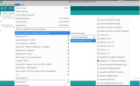
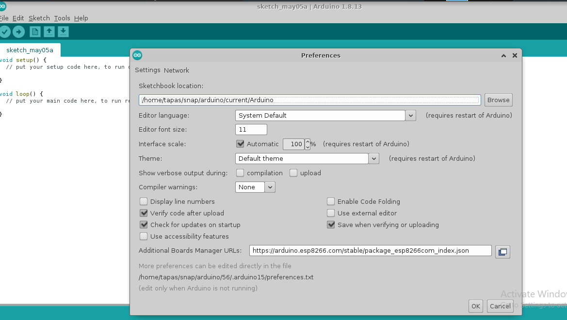
Follow the images below and read guidelines below each picture Arduino IDE, go to File> Preferences
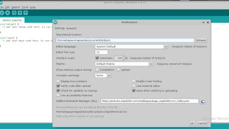
Figure: Enter http://arduino.esp8266.com/stable/package_esp8266com_index.json into the “Additional Boards Manager URLs” field as shown in the figure below. Then, click the “OK” button:
if you already have configured e.g. ESP32 boards URL,
you can separate the URLs with a comma as follows:
https://arduino.esp8266.com/stable/package_esp8266com_index.json
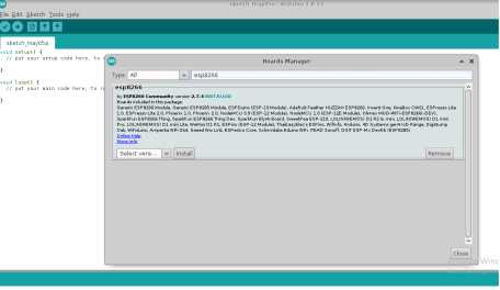
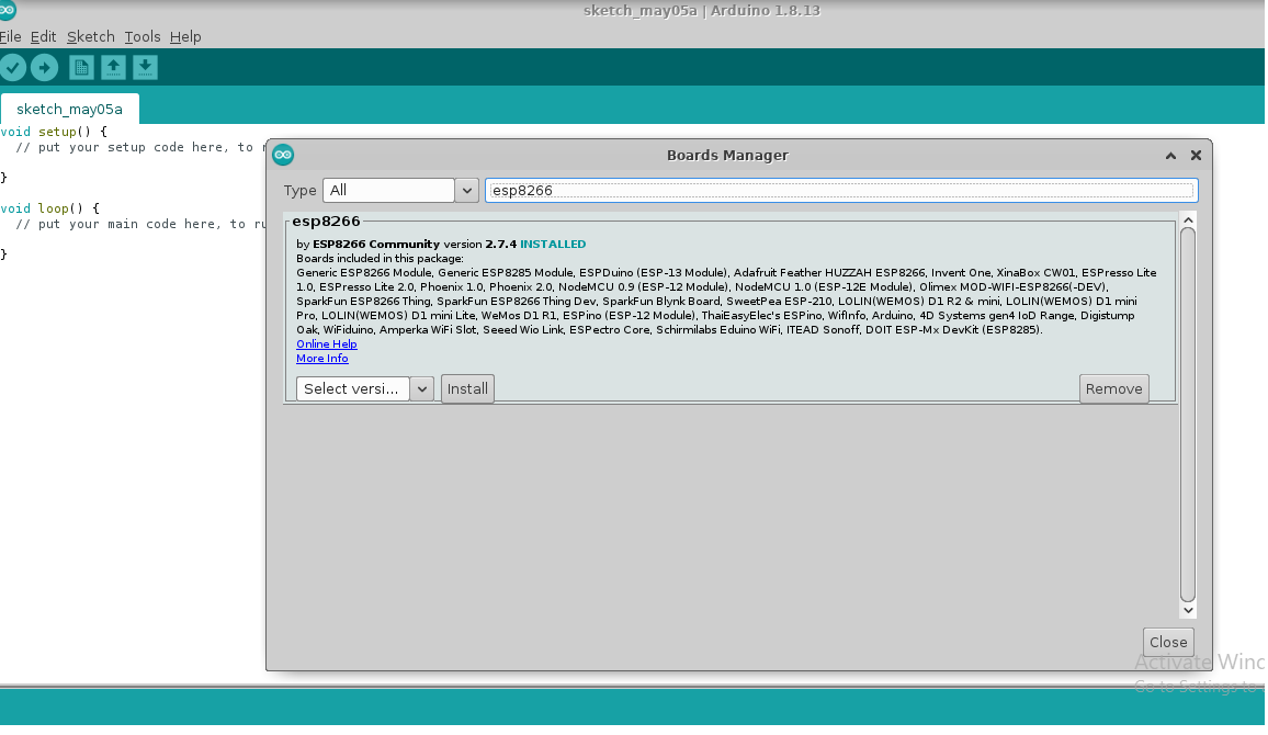
Figure: Open the Boards Manager in Arduino IDE: Go to Tools > Board > Boards Manager
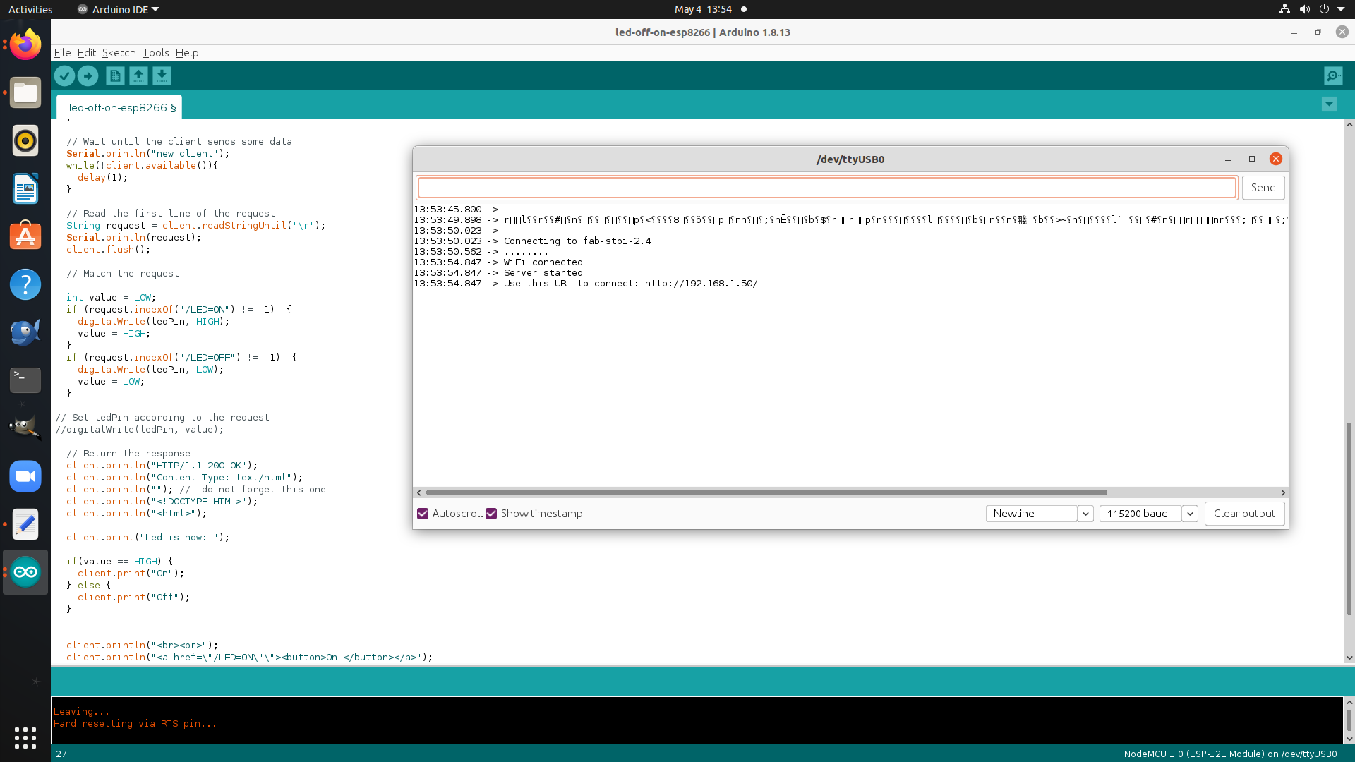
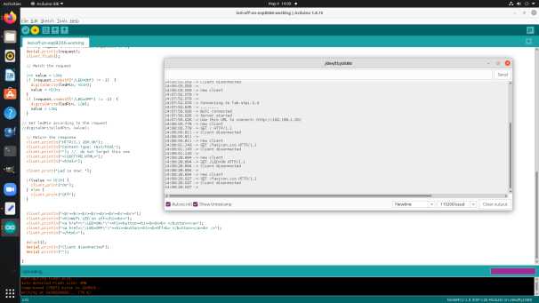
Program NodeMCU esp8266
#include <ESP8266WiFi.h>
#include <WiFiClient.h>
const char* ssid = "fab-stpi-2.4";
const char* password = "coolship738";
int ledPin = 13; // GPIO13---D7 of NodeMCU
WiFiServer server(80);
void setup() {
Serial.begin(115200);
delay(10);
pinMode(ledPin, OUTPUT);
digitalWrite(ledPin, LOW);
// Connect to WiFi network
Serial.println();
Serial.println();
Serial.print("Connecting to ");
Serial.println(ssid);
WiFi.begin(ssid, password);
while (WiFi.status() != WL_CONNECTED) {
delay(500);
Serial.print(".");
}
Serial.println("");
Serial.println("WiFi connected");
// Start the server
server.begin();
Serial.println("Server started");
// Print the IP address
Serial.print("Use this URL to connect: ");
Serial.print("http://");
Serial.print(WiFi.localIP());
Serial.println("/");
}
void loop() {
// Check if a client has connected
WiFiClient client = server.available();
if (!client) {
return;
}
// Wait until the client sends some data
Serial.println("new client");
while(!client.available()){
delay(1);
}
// Read the first line of the request
String request = client.readStringUntil('\r');
Serial.println(request);
client.flush();
// Match the request
int value = LOW;
if (request.indexOf("/LED=ON") != -1) {
digitalWrite(ledPin, HIGH);
value = HIGH;
}
if (request.indexOf("/LED=OFF") != -1) {
digitalWrite(ledPin, LOW);
value = LOW;
}
// Set ledPin according to the request
//digitalWrite(ledPin, value);
// Return the response
client.println("HTTP/1.1 200 OK");
client.println("Content-Type: text/html");
client.println(""); // do not forget this one
client.println("<!DOCTYPE HTML>");
client.println("<html>");
client.print("Led is now: ");
if(value == HIGH) {
client.print("On");
} else {
client.print("Off");
}
client.println("<br><br><br><br><br><br><br><br>");
client.println("<h1>WiFi LED on off</h1><br>");
client.println("<a href=\"/LED=ON\"\"><h1><button><h1><b>On<b> </button></a>");
client.println("<a href=\"/LED=OFF\"\"><h1><button><h1><b>Off<b> </button></a><br />");
client.println("</html>");
delay(1);
Serial.println("Client disonnected");
Serial.println("");
}

Initially in this week i have completed above work however my
remote instructor told me that it is needed to complete the the assignment by doing communication between at least two micro controller the same i
also understand and work out on that it is very interesting so i have decided to communication between two Micro controller i.e Attiny 44
In WEEK-6-Electronic Design i have been designed the hello ckt board that circuit board is using for this assignment
Serial communication Vs Parallel communication:-
Parallel interfaces transfer multiple bits at the same time. They usually require buses of data - transmitting across eight, sixteen, or more wires. Data is transferred in huge, crashing waves of 1's and 0's.
Parallel communication certainly has its benefits. It's fast, straightforward, and relatively easy to implement. But it requires many more input/output (I/O) lines.
Serial interfaces stream their data, one single bit at a time. These interfaces can operate on as little as one wire, usually never more than four.
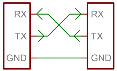
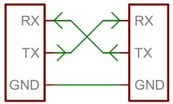
Serial interfacing is like what we have done in most of the boards we made in Fab Academy like (Hello Echo) to send signal through one pin which is Tx and receive the signal through another pin which is Rx. So it make it simple instead of using one board and FTDI
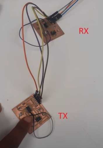
I will be using two boards and connect Tx of the 1st board to Rx of the second board and vice versa.
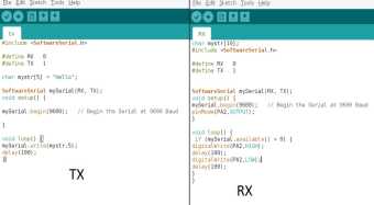
I wrote the above code by configuring
the Tx and Rx pins at each board, sending Hello from the tx board, Receiving the serial data from the rx board that has a LED and if there were data through
serial bus the LED should blink. I uploaded the code using my Fab ISP on both of the boards then I
connected then to each other using the serial connection TX,RX,VCC,GND.

I switched the tx and the rx boards. Made the board with the LED and the push button is the tx that sends the node number and confirm its sending by blinking a led. And made the other board as the rx that receives the signal and confirms receiving by send message through the serial monitor.
Click to download the files :
website reference:-
https://lastminuteengineers.com/esp8266-nodemcu-arduino-tutorial/
https://diyi0t.com/esp8266-nodemcu-tutorial/
https://circuits4you.com/2018/02/20/esp8266-arduino-digital-io/
https://learn.sparkfun.com/tutorials/serial-communication

if you already have configured e.g. ESP32 boards URL, you can separate the URLs with a comma as follows:
https://arduino.esp8266.com/stable/package_esp8266com_index.json

#include <WiFiClient.h>
const char* ssid = "fab-stpi-2.4";
const char* password = "coolship738";
int ledPin = 13; // GPIO13---D7 of NodeMCU
WiFiServer server(80);
void setup() {
Serial.begin(115200);
delay(10);
pinMode(ledPin, OUTPUT);
digitalWrite(ledPin, LOW);
// Connect to WiFi network
Serial.println();
Serial.println();
Serial.print("Connecting to ");
Serial.println(ssid);
WiFi.begin(ssid, password);
while (WiFi.status() != WL_CONNECTED) {
delay(500);
Serial.print(".");
}
Serial.println("");
Serial.println("WiFi connected");
// Start the server
server.begin();
Serial.println("Server started");
// Print the IP address
Serial.print("Use this URL to connect: ");
Serial.print("http://");
Serial.print(WiFi.localIP());
Serial.println("/");
}
void loop() {
// Check if a client has connected
WiFiClient client = server.available();
if (!client) {
return;
}
// Wait until the client sends some data
Serial.println("new client");
while(!client.available()){
delay(1);
}
// Read the first line of the request
String request = client.readStringUntil('\r');
Serial.println(request);
client.flush();
// Match the request
int value = LOW;
if (request.indexOf("/LED=ON") != -1) {
digitalWrite(ledPin, HIGH);
value = HIGH;
}
if (request.indexOf("/LED=OFF") != -1) {
digitalWrite(ledPin, LOW);
value = LOW;
}
// Set ledPin according to the request
//digitalWrite(ledPin, value);
// Return the response
client.println("HTTP/1.1 200 OK");
client.println("Content-Type: text/html");
client.println(""); // do not forget this one
client.println("<!DOCTYPE HTML>");
client.println("<html>");
client.print("Led is now: ");
if(value == HIGH) {
client.print("On");
} else {
client.print("Off");
}
client.println("<br><br><br><br><br><br><br><br>");
client.println("<h1>WiFi LED on off</h1><br>");
client.println("<a href=\"/LED=ON\"\"><h1><button><h1><b>On<b> </button></a>");
client.println("<a href=\"/LED=OFF\"\"><h1><button><h1><b>Off<b> </button></a><br />");
client.println("</html>");
delay(1);
Serial.println("Client disonnected");
Serial.println("");
}